Earth Tester Circuit Diagram
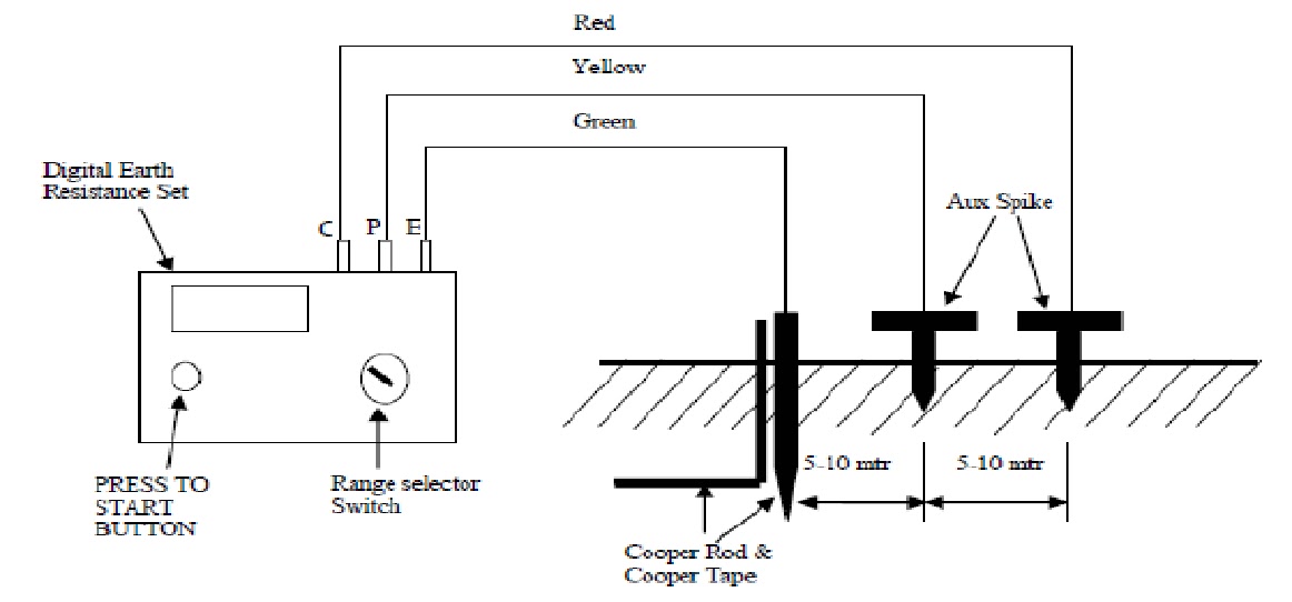
Measurement of earth resistance by potential fall method Schematic diagram of earth tester. Earth tester circuit diagram
Measurement of Earth Resistance by Potential Fall Method - Meaning
What is earth tester? From the q and a Earthing circuit diagram
Earth leakage tester circuit diagram
Megger construction circuit working coil definition magnetic circuitglobeHow to measure earth resistance through megger Earth tester : procedure to measure earth resistance and its applicationsEarth resistance tester circuit diagram.
Using the earth tester ft6031: three-pole methodLive, neutral, earth fault indicator circuit 2 simple earth leakage circuit breaker (elcb) explainedMegger circuit diagram.

Earth tester
Principle of earth resistivity measurements – earth expressEarth tester Digital earth tester diagramTester socket.
Earth tester circuit diagramCircuit elcb simple leakage earth homemade circuits breaker electronic diagram hobby projects electronics phase diy Tester schematicEarth resistance measurement using digital earth tester.

[diagram] milling machine alignment test report with diagrams
Earth resistance tester principle working test measure arduino current fig voltage electrodes means transformer loop topic electrical board ammeter voltmeterEarth tester Earth resistance tester circuit diagram4 important methods of ground resistance testing.
Earth leakage tester circuit diagramResistance earthing measure electrical megger measurement ering perform Electric tester circuit diagramEarth point test ground three voltage soil tester current nutsvolts volts.

What is earth tester? working principle, construction, diagram
What is earth tester ? definition, construction, working and advantagesResistivity testers measurement principle formula mentioned Tester earth circuit construction current works dc rectifier circuitglobeEarth tester circuit diagram.
Earth tester or earth resistance testerPhase neutral ac socket outlet tester circuit Electrical topics: working principle of earth resistance testerEarth circuit neutral fault live indicator diagram phase homemade pcb leakage ac circuits led leds projects wrong indications using.

What is megger?
Earth resistance digital meter connection diagram & working principle.Earth tester resistance ground circuit From the q and a.
.


![[DIAGRAM] Milling Machine Alignment Test Report With Diagrams](https://i2.wp.com/media.megger.com/mediacontainer/medialibraries/megger/images/electrical tester10/det-operation2.gif)